The final data logger with clamps to connect to the car battery. An extra fuse was built into one of the battery connectors to protect against insulation break-down.
More often than convenient I used to find my car battery drained and the car unable to start after a long period of disuse. In order to find out if there was a short circuit or power leak somewhere, if the battery was simply too old, and to test the charging functionality in the car, I decided to monitor the battery voltage over a long time.
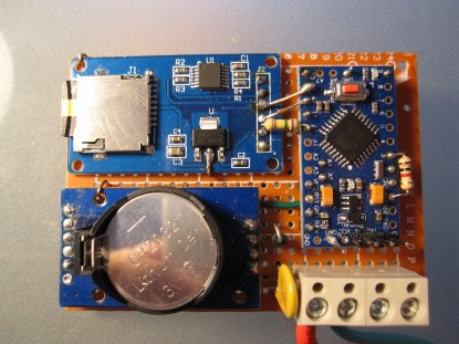
Luckily I found this great Arduino Data Logger project which delivered the schematics and components. The core of the electronics are three devices: the Arduino ProMini microcontroller (for doing computation and voltage measurement), the SD card reader (which can be still reduced from the one used here), and a real-time clock (RTC) module for triggering a data write every second.
Here I put these components on one breadboard.

Final SD-card voltage logger assembly on one breadboard
I used the code here and instead of using an external analog to digital converter (ADC), I used the ProMini built-in ADC with a voltage divider that would allow me to measure up to roughly 18 Volts (just to account for any high voltage is when starting the car and charging). Only one resistor of that voltage divider is visible here going to the ProMini board.
Take note, that indeed it is necessary to remove the trace that is supposed to charge the (often sold non-rechargeable) button cell in the real-time clock module.
Unlike the original project I could count on a relatively reliable power source – the car battery itself. I was not interested measuring the battery when it’s voltage already dropped below 5V. Therefore I only made sure that the battery was above a certain value (4.2V) when the microcontroller was turned on, in order to avoid write errors on the SD card.
I also used the 3.3V regulator on the SD card for powering the rest of the board (ProMini, RTC, and of course SD-card). This came particularly handy as the regulator on the ProMini board did not perform too well with voltages below 5V.
I furthermore added a diode (to avoid the device blowing up when used in wrong polarisation) and a polyfuse for extra security. These are located right next to the the battery input terminals. Note that only two of the 4 terminals were actually used.
I actually did not make proper schematics of this particular instance, but if you have questions or are interested how this actually goes together feel free to drop me an email!
